
- +41 78 638 07 09
- + (41) 78 638 07 09
- Safe and Ultra-precision Electronic Overspeed Protection
- Products & Solutions

Overspeed protection system
What is overspeed protection.
Overspeed protection is a system for rotating machinery such as turbines, generators, and motors that detects the overspeed and excessive acceleration conditions and then acts to prevent damage and downtime. Due to the cost of turbines or other rotating machinery equipment, utilizing a reliable and safe overspeed protection system is very important.

What is turbine overspeed test?
A set point that shows the maximum acceptable speed of the rotating machine should be set in overspeed protection system. If the speed of the turbine exceeds the set point value and the trip relay or circuit acts on time, overspeed test is passed , and if not the over speed is failed. It should be noted that during the overspeed test risk of loss of load should be considered.
What is electronic overspeed?
Overspeed protection system contains several electronic-based cards such as communication, relay, voter cards, and so on. The sensor signal is read by the electronic cards of the overspeed protection system, then by comparing the set and read value, a relay can close or open control valves.
What is an electronic overspeed trip?
There are two types of overspeed trips ; mechanical and electronic. In the electronic overspeed protection systems , a sensor measures the speed of rotating machinery gear and gives the system a sinusoidal or square wave, the speed has been determined by the system and thanks to the logic and trip relay section, the electronic overspeed trip mechanism is utilized. Due to the necessity of safety in these types of systems, a redundant voter structure is used.
Each rotating machinery, either heavy such as turbines and generators, or light such as diesel motors and generators, should be driven on specified condition and their rotational speed should not exceed the set value. There are a lot of crashes in the power plant and other utilities due to the rotating machinery overspeed event. Utilizing overspeed protection systems in turbine and generator units in power plants is very important because any crashing and failing of these units has a considerable cost.
Designing and implementing the overspeed protection systems is not easy in a way that designers should consider related standards such as API 670 which explains the minimum requirements for machine protection systems like electronic overspeed detection, logic and control separation, and response time. Moreover, due to the expensive equipment which is installed in power plants, oil refinery sites, and other utilities all of the protection systems should be designed and implemented by considering SIL requirements.
There are well-known companies around the world that design overspeed protection systems like Bentley Nevada, Braun, Isetec, and Emerson. The latest version of Bentley Nevada’s overspeed protection system is the 3500 machinery protection series. E16X series is the Braun overspeed protection system. Also, Woodward’s overspeed protection system is PROTECH-GII. Also, the CCC introduces its overspeed detection system as the Guardian overspeed protection system. All of the mentioned systems are utilized for generator overspeed protection, steam turbine overspeed protection, and gas turbine overspeed protection.
Rayan P-10 Product
The RAYAN-P10 Overspeed Protective Equipment is a product developed by HANI Energy Co. It is intended to be used for rotating machines Overspeed protection.
Overspeed Protection Device reads the frequency of input sensors by 3 independent Monitoring modules and trip two 2oo3 voters if at least two sensors detect over frequency(Electronic overspeed trip) from user setpoint. In this SIL3 overspeed protection device, each monitoring module reads two other sensors for comparison and sensor fault detection. In addition the monitoring modules support an isolated power supply for sensors that need to be powered. In this case a current monitoring of sensor is done to detect faults of sensor(overspeed trip). For safety path, measuring, comparison and deenergizing the shutdown relays, is tested by a self-test process in each Speed Monitoring and Protection Systems for Rotating Equipment. If any fault detected the module would be forced to trip mode. Electronic Overspeed Trip Device can monitor up to two shaft speeds in the same rack (2 set of 2oo3 overspeed protection can be assembled on one rack). Each set of overspeed can be set by unique overspeed setpoints. The Monitoring modules and voters of two sets are independent in this safety protection devices.
There is a TFT LCD and keypad Module (IM) for displaying the status of monitoring modules, alarms and events, and also setting the user configurations. This display part is out of safety path and only used for monitoring.
A profibus communication port exists in this overspeed protective devices for sending data of IM to user system. All the displayed data on IM module can be read in profibus, but user settings can’t be set by this port.
In addition to IM module, a powerful PC software, Raylink, connects to system through Ethernet port, for programing the user settings or read the settings recently set on system, this user friendly software enable the user to fast configuration for overspeed safety equipment.
Product Features:
– Fast reaction time to turbine overspeed trip (15msec) – Two Internal 2oo3 voting relays – Isolated analogue outputs with scalable ranges for each monitoring module – Peak speed detection and display – Front panel TFT display – One External-trip input – Two alarm output – A buffered output pulse – Independent power input (18–30 V DC) for each Module – The input can read magnetic pickup, proximity and hall effect sensors – Hot pluggable modules – Up to two shaft monitoring and trip on one rack – Alarm management and event logger consist of: – Speed deviation between input sensors – Check for communication loss – Out of range Setting Input – Speed measurement processor failure – Routine test performance – Power Monitoring – Configuration via PC and front panel LCD and keypad
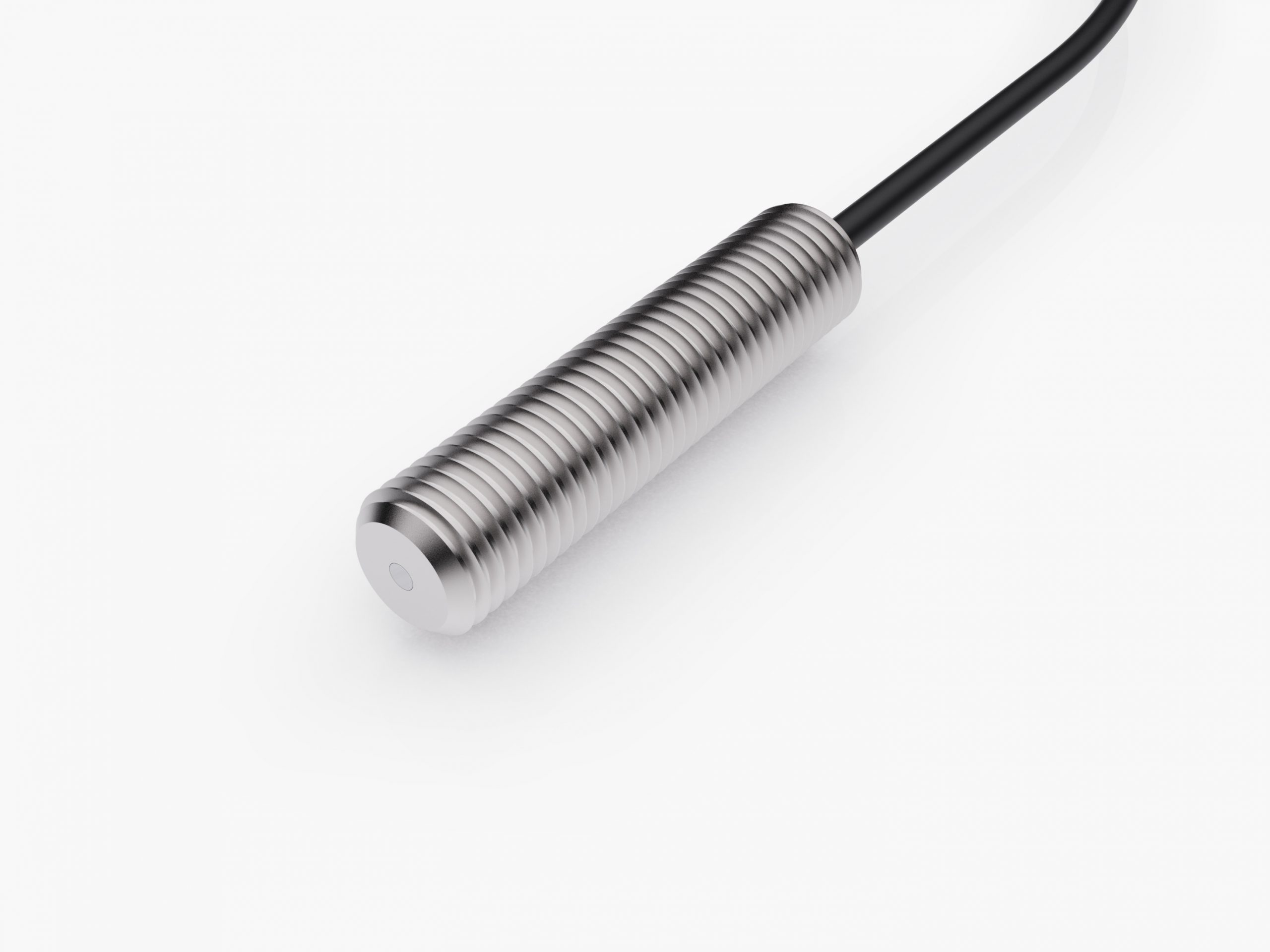
Speed Pickup Sensor
Rotating machinery requires speed sensing for speed control, monitoring, and Protection. Speed sensing is accomplished using a variety of technologies. Variable-reluctance based MPUs (magnetic pickups) are commonly selected because of their simplicity, reliability, and low cost. MPUs are passive probes in sense, that there are no active signal conditioning electronics in the probe. VR (passive) sensors also do not require an external supply, simplifying the overall system and increasing system reliability values.
Get in Touch
Royal Navy Ship HMS Trent Seizes Cocaine Worth £40 Million In The Caribbean Sea

Seafarers Hospital Society Launches Pilot Project To Support Women At Sea

Hydrocell Launches The First Hydrogen-Powered Boat

Indian Port Workers Call Off Strike After Agreeing To New Wage Settlement

Over Speed Trip in Diesel Engines & Types of Over Speed Trips
An over speed trip is a safety feature provided on the diesel engine of the ship to restrict uncontrolled acceleration of the engine, leading to mechanical failure or untoward accidents. In order to prevent the speed of a diesel engine to go beyond the pre-set speed range, an over speed trip is used in the diesel engines.
How Over Speeding can be Harmful?
A Diesel engine is designed for the mechanical stress associated with the centripetal and centrifugal forces of the moving parts inside it in a specified operational range. Centripetal force is directly proportional to the square of the rotational speed, stress increases rapidly with increase in speed. Mechanical connection strength can be overcome by the exceeding stresses due to the increase in operational speed. These can result in breaking of rotating parts or damage to the machinery itself. Over speed is thus a serious safety hazard and can lead to a fatal situation.

What does Over Speed Trip Does?
Due to sudden changes in the load on the diesel engine, the speed of the engine may vary. Though a governor is provided to control the speed of the diesel engine, the speed might go out of control, damaging the engine. Thus, for this reason over speed trips are used.
No matter what type of the over speed trip the engine uses, the main aim of the over speed trip is to cut the fuel supply to the engine cylinders in case the engine speed rises above a specific level.
Preventing Over Speeding of Engine
Reducing the likelihood of an uncontrolled and catastrophic over speed is essential and can be done by two methods:
a) Mechanical over speed trip
b) Electronic over speed trip
In this article we will have a look at the electronic over speed trip.
Electronic Over Speed Trip
To understand the electronic over speed trip, a normal lay out of the system is described below. The electronic over speed trip consists of
a) Fly wheel mounted speed sensor
Magnetic speed sensor is preferred in generator engines. Due to the discontinuity of actuator surface (gear tooth of flywheel) voltage is excited in the pick off coil of sensor, producing an electric analog wave. This cyclic wave created by the flywheel is read by the sensor.
b) Signal condition unit
This unit act as a receiver to the speed sensor. Basic function of the signal conditioner is to convert one type of electronic signal which may be difficult to read into another type into a more easily read format. This can be achieved by amplification, excitation and linearization of an electrical signal.
c) Detection and Comparison unit
There is a set value which is normally 10 % above the rated speed and acts as base value for this unit. Signal condition unit output is continuously detected and compared with the set value.
d) Trip signal unit
If the difference between the set value and detected value is above the limit, then this unit gives a trip signal which in turn shuts down the generator.
Disclaimer : The information contained in this website is for general information purposes only. While we endeavour to keep the information up to date and correct, we make no representations or warranties of any kind, express or implied, about the completeness, accuracy, reliability, suitability or availability with respect to the website or the information, products, services, or related graphics contained on the website for any purpose. Any reliance you place on such information is therefore strictly at your own risk.
In no event will we be liable for any loss or damage including without limitation, indirect or consequential loss or damage, or any loss or damage whatsoever arising from loss of data or profits arising out of, or in connection with, the use of this website.

Do you have info to share with us ? Suggest a correction
Daily Maritime News, Straight To Your Inbox
Sign Up To Get Daily Newsletters
Join over 60k+ people who read our daily newsletters
By subscribing, you agree to our Privacy Policy and may receive occasional deal communications; you can unsubscribe anytime.

About Author
An ardent sailor and a techie, Anish Wankhede has voyaged on a number of ships as a marine engineer officer. He loves multitasking, networking, and troubleshooting. He is the one behind the unique creativity and aesthetics at Marine Insight.
Read More Articles By This Author >

BE THE FIRST TO COMMENT
24 comments.
can you send to me mechanical over speed tripper journals and drawbacks…
hello sir, i want to know , how main engine overspeed trip is tested & what is the time duration of testing
Dear Pundari,
It is better to test the functioning of the over speed trip rather testing it at its real set speed. The set point is lowered then the required speed. once the generator reaches this lowered set point, it will trip. To run the generator in the actual overspeed condition is dangerous and long run in such speed can lead to problem in the bottom end bolts of the con rod.
anish, good day sir. im working in a ship, our aux generator is running but its not getting a load. the generator is running fast in 5sec then it will go slowly, what is the problem of this. tnx
The problem seems to be with governor of the AE. Check the droop setting of the same.
With thanks for all above information , kindly note recently we faced with aux engine over speed on one o our fleet vessel an led to total failure , explosion and fire in engine room.
Same aux engine was repaired/overhauled just 20 days back of accident in repair yards. Over speed trip were not activated and cause explosion.
Kindly advise possible factors which to be consider for such big accident.
With many thanks in advance.
i am working on CAT engine its many time show over speed alarm i change relay but the problem still there let me know what is the main problem and i can diagnose i
THIS SIGHT IS GIVING VERY VALUABLE INFORMATION
Its good to finally find a site like this. THUMBS UP!!!
Please assist me with this issue, my 5 cylinder Sulzer Harbor Generator is starting, only to be tripped by the over speed device when attempting to attain its rated RPM of 760. I suggested that the UG 8 governor might be faulty. Please what seems to b the problem?
rly a good rply by this site
How i can test overspeed alarm in generator vatepillar c-18. Answer please.
Please can you kindly help me, there is a cummins gen, and it has been tripping on over speed. Please can you kindly assist/give me a better idear to sort out this problem..
Please Sir, I need possible remedy or solutions to overspeed shutdown of Cummins power generator.What are the curses of that over speed?
Reasons have already been listed in the article. Overspeeding of engine is not healthy for rotational part of the engine (bearing housing bolts, crankshaft and its bolts etc.)
A nice site, I’m working on CT6 with overspeed issue… Have adjusted the Woodward the problem still persist, what really the possible causes?
We have created online forums for such technical discussions. Please visit: https://forums.marineinsight.com
You can contact any time related with all type of Woodward governing system and caterpillar engines related Quires, My contact Number is +91 9987396573
Good day Please is it possible test over speed from PLC
@Alan: in Many engine circuit, a test knob is provided. You can use that to test the overspeed trip.
How to reset mechanical overspeed trip
8 DK28 daihatsu generator engine .how to try out overspeed trip.i have a sensor in in flywheel so it may be a electronic type .how to carry outtests can somebody help sharing information?
@Benasher: Usually, the value of the speed sensor controller is reduced so that as the generator starts and reeatrip will operatoe ched the speed, the
Please comment on what to check in alternator…..
@Ankit: Please check this article- https://www.marineinsight.com/tech/generator/important-points-while-carrying-out-alternator-maintenance-of-ships-generator/
Leave a Reply
Your email address will not be published. Required fields are marked *
Subscribe to Marine Insight Daily Newsletter
" * " indicates required fields
Marine Engineering
Marine Engine Air Compressor Marine Boiler Oily Water Separator Marine Electrical Ship Generator Ship Stabilizer
Nautical Science
Mooring Bridge Watchkeeping Ship Manoeuvring Nautical Charts Anchoring Nautical Equipment Shipboard Guidelines
Explore
Free Maritime eBooks Premium Maritime eBooks Marine Safety Financial Planning Marine Careers Maritime Law Ship Dry Dock
Shipping News Maritime Reports Videos Maritime Piracy Offshore Safety Of Life At Sea (SOLAS) MARPOL
- Power Generation
- Authorizations
- SCN – Service Company Network
- Automation & Electrical Support
- On-Site/In-Situ
- Duap Fuel Injection Systems
- Mechanical Services
- Ultrasonic Inspection
- Turbocharger Sales & Support
- Turbocharger Repair & Maintenance
- Turbochargers Spares Parts
- Turbocharger Retrofit Solutions
- Filtration & Separation
- Safety & Monitoring Systems
- Compressor, Coolers & Deck Equipment
- Control Systems
- Schaller Automation – Oil Mist Detectors
- Marine Electrical Services
- Vessel Re-Power
- Marine Mechanical Services
- Marine Diesel Engine Propulsion Systems
- Marine Engine Dealer Map
- Governor Exchanges and Remanufactured Sales
- Catalyst Maintenance Services
- Maintenance and System Health Review
- Turbine Fuel Valve Repairs
- Control System Integration
- Control Modernization & Retrofit
- Life Cycle Support
- Technical Support
- Control System Service
- Installation & Commissioning
- Mechanical Designs
- Vibration Monitoring Systems and Analysis Services
- Daihatsu Diesel
- MAN Energy Solutions
- S.E.M.T. Pielstick
- YANMAR Marine
- Hyundai HiMSEN
- Mitsui Two-Stroke Engines
- KBB Turbochargers
- MET Turbocharger
- GEA Westfalia Separators
- Hatlapa Compressors
- GEA – Heat Exchangers
- CM Technologies
- ZF Marine Propulsion Systems
- Gas Engine Products
- Gas Turbine Products
- Power Management Products
- Compressor Surge Controls
- New Woodward Products
- Diesel Engine Products
- Steam Turbine Products
- Hydro Control Systems
- Dual-Fuel & Bi-Fuel Systems
- DCL QUICK-LID Catalysts and Silencers
- Continuous Catalyst Monitoring System (CPMS)
- DCL MINE-X Catalysts
- DCL Diesel Particulate Filters
- Heat Exchangers
- Selective Catalyst Reduction (SCR) Systems
- Catalyst Replacement Elements
- Siloxane Removal Technology (SRT)
- KRAL Fuel Measurement
- Speed Monitoring
- Vibration Monitoring Systems
- Dynalco Meters & Sensors
- Schaller Oil Mist Detectors
- MSHS HMI and SCADA Systems
- Schaller ACCOMOS®
- Horner Automation
- Auto-Maskin
- Ingersoll Rand Air Starters
- TDI Air Starters
- Retrofit and Adapter Kits
- AVRs & Excitation Systems
- Engine Spare Parts
- Reconditioned Components
- Descriptions
- Schedule 2024
- Custom Training
- Registration
- Request Form
- News & Events
- Bergen Engines
- Hedemora Turbochargers
- Vestas Aircoil – Heat Exchangers/Charge Air Coolers
- SEG Protection Relays
Overspeed Safety Systems for Steam Turbines
The platform ranges from the simplex version (ProTech-SX) to a full TMR based control that also monitors up to 10 different machinery sensors/devices (ProTech TPS) to provide a full blanket of protection for your equipment. The new platform leverages decades of experience from Woodward’s ProTech 203 platform. Many improvements to the platform make it easier to use, maintain, customize, and standardize. In addition, security functionality is implemented to meet the market’s new Cyber Security requirements.

MicroNet™ Safety Module
Woodward’s MicroNet™ Safety Module PLC can be applied to any size steam, gas, or hydro turbine, or plant process equipment. This safety PLC’s fast (12 millisecond) response time, 0.5 to 32 000 rpm speed range, and integrated overspeed and acceleration detection/protection functionality, make it ideal for application on critical high-speed rotating motors, compressor, turbines or engines.The Micronet™ Safety Module is IEC61508 SIL-3 Certified and API670 & API612 Compliant.

ProTech®-SX Safety System with Integrated Overspeed Protection
The Woodward ProTech-SX is a safety programmable logic controller (PLC) with integrated overspeed protection designed to safely shut down any plant process equipment, engine, or steam, gas, or hydro turbine upon sensing a safety event. This stand-alone safety system accepts two speed inputs and seven discrete/analog inputs, uses programmed logic to determine when a safety event has occurred, then issues system shutdown commands and alarms. The Woodward uses five fast-acting, configurable relay ouputs and a speed meter output to interface with/command the specific system or device being protected.

ProTech®TPS Total Protection System
The Woodward ProTechTPS safety system is designed to be applied as a safety system for any size steam, gas, or hydro turbine, or plant process equipment. This safety PLC’s fast(10 millisecond) response time, 0.5 to 32 000 rpm speed range, and integrated overspeed and acceleration detection/protection functionality, make it ideal for application on critical high-speed rotating motors, compressor, turbines or engines.
ProTech®-GII Overspeed Protection Device
The Woodward ProTech®-GII Overspeedis an overspeed safety device designed to safely shut down steam, gas, and hydro turbines of all sizes upon sensing an overspeed or overacceleration event. This device accurately monitors turbine rotor speed and acceleration via active or passive magnetic pickups (MPUs) and issues a shutdown command to the turbine™s trip valve(s) or corresponding trip system.
QuickTrip - Trip Block Assembly
Safety certified hydraulic trip block assembly for use in industrial steam turbine shutdown systems. The QuickTrip trip block assembly is designed for use in steam, gas, and hydro turbine shutdown systems for quick and reliable dumping of the turbine’s trip oil header. This integrated trip block assembly is intended for use on mechanical-drive or generator-drive steam turbines that use low pressure (5-25 bar / 73-363 psi) hydraulic trip oil headers. The QuickTrip’s fault tolerant design makes it ideal for critical steam turbine applications, where turbine up-time and availability are essential. This trip block assembly’s 2-out-of-3 voting design provides users with a very high level of system reliability as well as compliance with industry standard API-670. Certified for use in IEC61508 SIL-3 systems.

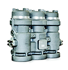
H-Block Trip Valve
The MSHS H-Block trip manifold is designed to provide a pre-packaged 4-valve trip arrangement, thus simplifying installation for the end-user. Simplifying the packaging of [4] trip valves in [1] housing keeps already complex systems in turbine trip headers from becoming confusing and helps to avoid nuisance trips.
Ready to serve you
Full service locations in Southeast, the Gulf Coast, and the Pacific Northwest, plus a network of local representatives throughout the Americas and the Caribbean.
Estamos disponible para servirle Instalaciones de servicio completo en el Sureste; Costa Noroeste, y El Golfo. Además una red de agentes en América Latina y el Caribe.
Please complete the form below. Non-Emergency Requests Only.
Specializing in turnkey engine services, control systems, and engineered solutions for the Marine, Industrial, Energy, and Defense/Government Sectors, MSHS is ready to serve you!


OR WAIT null SECS
- Do Not Sell My Personal Information
- Privacy Policy

© 2024 MJH Life Sciences ™ and Turbomachinery Magazine . All rights reserved.
How steam turbine protection system works
The function of the steam turbine protection system is often confused with the control system, but in fact the two systems are entirely separate. The protection system operates only when any of the control system set point parameters are exceeded, and the steam turbine will be damaged if it continues to operate.
A multi-valve, multi-stage turbine protection system incorporates a mechanical overspeed device (trip pin) to shut down the turbine on overspeed (10 percent above maximum continuous speed).
The protection system monitors steam turbine total train parameters and ensures safety and reliability by the following action:
Start-up (optional) provides a safe, reliable fully automatic start-up and will shut down the turbine on any abnormality
Manual shutdown
Trip valve exerciser allows trip valve stem movement to be confirmed during operation without shutdown
Rotor overspeed monitors turbine rotor speed and will shutdown turbine when maximum allowable speed (trip speed) is attained
Excessive process variable signal monitors all train process variables and will shutdown turbine when maximum value is exceeded
Centrifugal force resulting from high shaft speed will force the trip lever, which will allow the spring loaded handle to move inward. When this occurs, the port in the handle stem will allow the control oil pressure to drain and drop to zero. The high energy spring in the trip and throttle valve, normally opposed by the control oil pressure will close suddenly (less than one second). In this system there are two other means of tripping the turbine (reducing control oil pressure to zero) – manually pushing spring loaded handle and solenoid valve opening.
The solenoid valve will open on command when any trip parameter set point is exceeded. Solenoid valves are designed to be normally energized to close. In recent years, the industry has required parallel and series arrangements of solenoid valves to ensure increased steam turbine train reliability. Today, most speed trip systems incorporate magnetic speed input signals and two out of three voting for increased reliability. The devices that trip the turbine internally directly reduce the control oil pressure, causing a trip valve closure without the need of a solenoid valve (external trip method).
Two popular types of steam turbine shut off valves are available and both use a high spring force, opposed by control oil pressure during normal operation, to close the valve rapidly on loss of control oil pressure.
It is important to note that the trip valve will only close if the spring has sufficient force to overcome valve stem friction. Steam system solid build up, which increases with system pressure (when steam systems are not properly maintained), can prevent the trip valve from closing.
To ensure that the trip valve stem is free to move, all trip valves should be manually exercised on-line. The recommended frequency is once per month for High Pressure (40 bar) steam systems and daily for very high pressure (1000 bar +) steam systems. All the turbine trip valves should be provided with manual exercisers to allow this feature.
It can be hard to maintain VHP (very high pressure) steam systems, and to prevent contaminants (calcium, silica) from forming inside the turbine. Trip valve packing is essentially a filter that will trap any contaminants between the trip valve and the packing which can prevent the trip valve from closing.
Failure of the trip valve to close on command can cause catastrophic machine failure and expose personnel to safety issues. Periodic or infrequent exercise of trip valves can result in failure of the valve to move which, considering the plant safety requirements, will necessitate immediate turbine shutdown. Daily exercise of VHP trip valves will ensure freedom of movement of the trip valve and positively prevent unnecessary unit shutdowns.
This best practice has been recommended since the 1990s. When followed, it has resulted in zero lost time accidents and failure to trip incidents. When not followed, more than one catastrophic machine outage in critical (un-spared) machinery has occurred, that has exceeded three months in repair time.
Related Content:

- Emerson.com
- About the Blog
Electronic Turbine Overspeed Protection
by Jim Cahill | Aug 1, 2018 | Asset Management , Control & Safety Systems | 0 comments
At the 2018 Ovation Users’ Group Conference, Emerson’s Sam Onuska and Greg Lieb presented improvements in advanced overspeed protection and online, real time testing of overspeed systems.
Greg opened describing where overspeed protection systems can be applied including steam turbines, gas turbines, boiler feed pump turbines (BFPTs) and hydro turbines. These systems measure the shaft rotational speed and decide & take action based on overspeed conditions by providing a method to reduce rotational velocity.
Here’s a view of a typical mechanical overspeed system:
During an upgrade the trip lever and all associated linkages, hydraulic trip valve, pressure switches and tubing associated with the mechanical overspeed trip, reset and test are removed. Typically, the rotor-mounted equipment remains due to rotor balance considerations and costs versus benefits of removal.
Components of an Electronic Turbine Overspeed Protection system include speed probes—Eddy current, Hall-Effect, or variable reluctance probes. The decision and action steps are automated within the electrical overspeed protection system. In the decision step, a pulse train or sine wave is converted to rotational speed and compared with a speed setpoint. In the action step, if the setpoint is exceeded a relay’s state is changes and voted or non-voted outputs sent to initiate a trip.
An independent overspeed controller has redundant power supplies, 3 dedicated overspeed sensing channels, 3 digital output I/O for all other Ovation trips and testable dump manifold (TDM) testing.
Modes of testing include offline card overspeed testing, online card overspeed testing, testable dump manifold trip, and turbine manual trip.
General guidelines for electronic overspeed protection systems are detection prior to 110-112% rated speed with the setpoints specific to the turbine make and model. Per the API 670-Machinery Protection Systems standard, overspeed reaction time should less than 40msec. The response to the observed overspeed condition should limit the speed to less than 120% of the rated speed. This response is influenced by the module configuration, sampling rate and rotor acceleration.
The total system response consists of overspeed detection, trip signal to hydraulic system and hydraulic actuator / valve closure.
The advantages of electronic systems vs. mechanical systems include no moving parts, common set of spares, no loss of production during testing, turbine not placed in unsafe conditions, tunability of the system, improved live data and historical view and fault tolerance.
Popular Posts
Share this:, subscribe to podcast.
We invite you to follow us on Facebook, LinkedIn, Twitter and YouTube to stay up to date on the latest news, events and innovations that will help you face and solve your toughest challenges.
Do you want to reuse or translate content?
Just post a link to the entry and send us a quick note so we can share your work. Thank you very much.
Our Global Community
Emerson Exchange 365
The opinions expressed here are the personal opinions of the authors. Content published here is not read or approved by Emerson before it is posted and does not necessarily represent the views and opinions of Emerson.
Privacy Policy | Cookie Policy | Data Protection Statement

What is Overspeed Trip, its types and how it works
- · Sudden removal engine load such as propeller coming out of water in rough weather, failure of clutch, fracture in a drive shaft of engine.
- · Stuck fuel control shaft.
Types of Overspeed Trips
Mechanical type overspeed trip.
Electro Pneumatic Overspeed Trip

Electronic Type Overspeed Trip
So this was all about the over speed trip that are used in the engines. If you want to add more info in to this topic ‘overspeed trips’, please feel free to comment below.

Related Articles

List of DG Approved Shipping Companies in India
In this article list of Shipping companies registered with DG shipping is given. The campanies here are separated on the basis of three regions Chennai, Mumbai and Kolkatta and RPSL numbers of shipping companies are also given below their names. Let’s see them one by one. DG approved shipping companies List of registered Shipping company in Chennai Tradex Shipping Co. (P) Ltd. RPSL-CHN-001 Adarsh Ship Management […]

IMO Sets 2020 For 0.5 % Sulphur Limit In Marine Fuel [Full Report]
In a recent move, international maritime organization has put .5% sulphur in the marine fuel oil cap. By 2020, all vessels have to comply with the above standard. This decision was taken in meeting held in London last week. What Does .5% Sulphur Marine Fuel Means This means that by 2020 every ship has to burn […]
MEO Class 4B Oral Questions|Operation of the Vessel and Safety of Personnel Onboard
In this post I have given the list of the questions that were asked in oral examinations of 4B. In this post I have picked some of the famous questions that were asked in the Operation of the vessel and safety of personnel onboard oral exams. Answer to these will be published shortly. If you have any […]
5 Replies to “ What is Overspeed Trip, its types and how it works ”
Hello, so the difference between the mechanical type overspeed trip and the electronical type overspeed trip is not the way that the turbine trips but taccuracy of speed sensing? in both systems the trip is achieved with the bolt ejecting out?
HI there all of the topics here are very important to us, how much it cost to subscribe or to buy a book from you.? GOD BLESS hope to hear from you soon.
- Pingback: Critical alarms and safety trips Critical alarms safety trips provided Safety
Hi everyone Please tell me how to do the main engine fuel pump plunger stuck during main engine operation in rough sea so can not stop ME Thanks in advance.
I think this is one of the most significant information for me. And i’m glad reading your article. But should remark on some general things, The web site style is perfect, the articles is really great : D. Good job, cheers
Leave a Reply Cancel reply
Your email address will not be published. Required fields are marked *
Save my name, email, and website in this browser for the next time I comment.
Cogent Purchasing Blog
Overspeed trip devices, their types, and functionality.
When operating a diesel engine of a vehicle or marine vessel, there is a chance that uncontrolled acceleration may occur. Uncontrolled acceleration can be highly detrimental to the engine assembly, potentially leading to mechanical failure or accidents. With the use of a component known as an overspeed trip, diesel engines can be safer to operate with the restriction of acceleration, even in the case of a failed diesel engine governor.
A rapid acceleration of a diesel engine can occur due to various reasons, one being the sudden removal of an engine load. For a marine vessel, this can occur when a propeller lifts over water during poor weather conditions, resulting in excess power. Additionally, the failure of a clutch or the fracturing of an engine drive shaft can also cause the sudden removal of an engine load. In other instances, overspeeding may also result from a stuck fuel control shaft.
Whenever a trip occurs, it will require manual resetting. This is due to the fact that an automatic reset may cause the engine to enter an overspeeding condition again if the issue is still present. Additionally, testing must be conducted on a regular basis to ensure proper functionality. To promote more guaranteed functionality, some engines will implement two overspeed trips that are independent from one another. One is an electro-pneumatic type, featuring a trip setting for 15% above nominal speed. The other device, meanwhile, is a mechanical type that has a trip setting for 18% above nominal speed.
Mechanical overspeed trip devices are fairly simplistic, often featuring a weighted spring loaded bolt that is set into the engine’s rotating shaft. As centrifugal force occurs, it is exerted on the bolt fitting. Once centrifugal force surpasses the preset spring force due to speeds exceeding the 15% rated speed threshold, the bolt will be ejected. At this time, the bolt will collide with a latch, resulting in the release of a plunger that stops the flow of fuel supply to the engine.
For electro-pneumatic overspeed trips, a spring loaded pneumatic cylinder is situated at each fuel pump. During standard operating conditions, the force exerted by the spring will maintain the positioning of the rod, preventing the operating end from making contact with the pin. When a trip condition occurs, a solenoid valve will force air into the cylinder, allowing for the piston to overcome the force of the spring. This will cause the piston rod to pull the pin of the fuel rack, moving it to a “no-fuel” position to stop the flow of fuel.
While mechanical and electro-pneumatic overspeed trip devices are quite common, electronic types are another option that one may use as well. With such devices, three magnetic pickups are monitored for overspeed protection. With their design, such devices excel in high speed applications such as steam or gas turbines. Additionally, electronic overspeed trip devices provide an increased amount of reliability over their mechanical counterparts.
With the proper implementation of overspeed trip devices, one can better protect their engine and all of its related components. At Cogent Purchasing, we are your sourcing solution for bearing engine components, plug overspeed trip parts, aircraft products, and so much more. Take the time to explore our vast catalog of parts at your leisure, and our team of industry experts are always on standby to assist you through the purchasing process however necessary. If you find particular items that you are interested in, take advantage of our RFQ service to quickly request quotes for your comparisons. Call or email one of our representatives at your earliest convenience and see how Cogent Purchasing can serve as your strategic sourcing partner for all your operational requirements.
- curtis barden
- Posted on October 20, 2021

What is the Importance of Primers in Aircraft Finishing
What Is a Jump Wire
Related Blogs
- Aircraft Engines
- aircraft parts
- Aircraft parts
- Aviation Part Types
- Electronics
- Electronics Components
Recent Blogs
Recent twitter posts.
All Orders are Fulfilled in the U.S.A.
All shipments must comply with U.S.A export laws.
No exceptions.

The only independent distributor with a NO CHINA SOURCING Pledge
“We Proudly Support Intrepid Fallen Heroes Fund that serves United States Military Personal experiencing the Invisible Wounds of War : Traumatic Brain Injury (TBI) and Post Traumatic Stress (PTS). Please visit website ( www.fallenheroesfund.org ) and help in their valiant effort”.
We Hope You Will Remember Us Next Time, If You’re Looking for NSN, Aviation, Electrical & Aircraft Chemical Parts.
We use cookies to ensure that we give you the best experience on our website. If you continue to use this site we will assume that you are happy with it.
- POWER Plant ID
- POWER Events
- Connected Plant
- Distributed Energy
- International
- COVID-19 Coverage
- Carbon Capture
- Climate change
- Cybersecurity
- Distributed Power
- Electric Vehicles
- Energy Storage
- Environmental
- Instrumentation & Controls
- Legal & Regulatory
- Legislative
- Ocean/Marine
- Physical security
- Plant Design
- Power Demand
- Research and Development
- Supply Chains
- Tidal Power
- Waste to Energy
- About POWER
- Privacy Policy
- Cookie Settings
- Diversity, Equity, Inclusion & Belonging
- Accessibility Statement
Replacing an HP/IP Rotor
Today’s power plant owners face many challenges, including the aging and degradation of equipment. Steam turbines at times may be condemned due to operating inefficiency or rising vibration levels. In such cases the options may be few because the turbine may require a full or partial rotor section replacement. The good news is that a rotor section replacement can be performed in a relatively short time, depending upon the original rotor configuration. Here’s one example.
During an outage in June 2008, a U.S. utility found during an inspection that its 100-MW steam turbine was in need of major repairs. A boresonic inspection detected ultrasonic indications near the bore, and for that reason the rotor could no longer operate at rated power. The only other option was a rotor replacement. In the meantime, the original equipment manufacturer proposed a temporary bottle bore repair to give the rotor sufficient remaining life to run while a new rotor could be manufactured.
Alstom was contacted and was asked for a proposal for a new high-pressure/intermediate-pressure (HP/IP) rotor, manufactured by join welding and modifying and welding multiple stock rotor forgings (Figure 1). The replacement rotor proved to be more cost-effective as a permanent repair and faster than replacement of the entire turbine mono-block forging. Essentially, raw forgings were welded together to form the skeleton of a replacement rotor, but in a fraction of the time necessary for an original forging to be procured.

Working with the Rotor
The rotor was next removed from the plant’s turbine casing before being transported to and received at Alstom’s repair facilities in Richmond, Va. Visual inspections were performed, complete measurements were taken, sample buckets were removed, and the rotor was blasted to clean and expose steeples.
Initially, blade rows 10 to 17 were to be refurbished, and new blades were to be manufactured for rows 1 to 9. However, it became more cost-effective, due to the condition of the components and shop scheduling, to manufacture all new rows of blades for rows 1 through 17.
The existing control shaft and overspeed trip assembly were nondestructively evaluated, and recalibration was performed on the overspeed trip assembly. Finally, low-speed balance-of-shaft components were completed.
The Replacement Rotor
The rotor forging sections were brought into the Richmond facility, set up and machined in the mill, and then the lathe was used to produce the join welding surfaces. After heat treatment of the welded rotor forging, the rotor’s wheels, dovetails, gland seals, and journals were completely machined. The coupling, balance weight holes, and steam balance holes were machined as part of the milling work (Figure 2).

The rotor dovetails were then shot-peened. The newly manufactured blades were installed, shrouds were manufactured and installed, and shroud covers were machined. The rotor was first balanced at operating speed and then at 20% overspeed. The replacement rotor was rebuilt from scratch in only six months, and the unit was quickly restored to service (Figure 3).

During a six-month period, two turbine forgings were join-welded and modified by weld build-up to the configuration of the existing rotor. Not only was extensive machining and weld build-up involved, but instead of refurbishment, all 17 rows of new blades (a total of 1,492 blades) were also manufactured and installed to replace the HP and IP straddle roots for the turbine rotor.
Such a solution provides steam turbine owners significant potential cost savings when compared to normal delivery cycles for a new fully bladed turbine rotor; it also avoids considerable purchased power costs.
— Contributed by Mike Jirinec , proposal manager, and James Heeter , business development manager for Alstom Power.
SHARE this article
- EMD Training
- Micellaneous
- Dash-2 Modules
- Axle Generators
- Event Recorders
- Microprocessor
- Rotating Electrical
- Traction Motors
- Locomotive Technical Publications
- Marine/Mining/Oil Drilling/Stationary
- New and Custom Design Parts
Additional Information
- Shipping & Returns
Account Navigation
Currency - all prices are in aud.

- Gift Certificates
- Sign in or Create an account

- Locomotive Parts
OVERSPEED TRIP ASSEMBLY (40013182)
")
Add to Wish List
Click the button below to add the OVERSPEED TRIP ASSEMBLY (40013182) to your wish list.

Product Description
Product reviews, write your own review.
We promise to never spam you, and just use your email address to identify you as a valid customer.
This product hasn't received any reviews yet. Be the first to review this product!
Find Similar Products by Category
Related products.

Further info
All prices are in USD . © 2024 LocomotivePartsOnline.com | Sitemap | Powered by BigCommerce
NSN 2825-01-200-8860 101C203AY, 101C203AYG1, 01-200-8860
- Part Directories
2825-01-200-8860
Product Details | STEAM TURBINE OVERSPEED TRIP ASSEMBLY
Part Alternates: 101C203AY, 101C203AYG1, 2825-01-200-8860, 01-200-8860, 2825012008860, 012008860
Engines, Turbines, and Components | Steam Turbines and Components
Cross Reference | NSN 2825-01-200-8860
Request a quote.

What Our Customers Say

Thank you very much for the excellent service and professional customer care.

The service was excellent. I can think of no improvements to date that you can make regarding internet sales.

The representative for WBParts was efficient & handled our request in a timely & professional manner.

Tried two other sources, neither of them responded, was all done online, never spoke to anyone.

The response is quick and the price is often very good. We are completely satisfied.
Related Products | NSN 2825-01-200-8860

Restrictions/Controls & Freight Information | NSN 2825-01-200-8860
- Restrictions
Management | NSN 2825-01-200-8860
- Body Controls
- Climate Controls
- Information Displays
- Instrument Clusters
- Power Locks/Kits
- Power Roofs
- Power Seats
- Power Steering
- ABS Modules
- ABS Module Bolt Kit
- Engine Control (ECU/ECM)
- Throttle Bodies / Kits
- Transmission Control (TCM)
- ALL PRODUCTS
- Testimonials & Reviews
- Top 5 Reasons to choose us
- How This Works
- Auto Shop Discounts
FIND YOUR MODULE

- Type Select Type ATV/UTV Car/Truck Motorcycle RV
- Year Select Year
- Make Select Make
- Model Select Model

WE REBUILD AUTO ELECTRONICS.
ABS Control Module Rebuilds

Instrument Cluster Rebuilds

Climate Control Module Rebuilds

Power Accessory Module Rebuilds

Powertrain Module Rebuilds

All Products

Popular Rebuilds

We are a team of electrical engineers and technicians who remanufacture automotive electronics. When your ABS light comes on, or your temperature controls stop working we can help. If the mechanic quotes you a high replacement cost, or you just can't find the part anymore check out our website for a low cost, sustainable alternative. You can remove the part and ship it to us yourself or ask your mechanic to do it for you. Still have questions? Give us a call, we're happy to help!

Seriously into modules since 2004
From its humble beginnings in 2004 operating out of his parent’s tiny pump house, Gavin Curtis grew ModuleMaster into a leading-edge technology company specializing in the repair of automotive electronics. Today, ModuleMaster operates out of two state-of-the-art facilities in Moscow, Idaho, home of the University of Idaho.
ModuleMaster receives over 1,000 modules a month including ABS controllers, instrument clusters, climate control modules, trip computers, and the list keeps growing.
Customer Testimonials
I have used module master on 2 occasions for my 2004 Chevy Suburban. The first time for the ABS module and the second time for the instrument cluster. In both cases both were repaired and returned quickly, both worked perfectly. I recommend module master without any reservations! Mike D. / Long Beach, CA
I sent Module Masters an instrument cluster to get repaired that had an ignition off draw which was not the normal gauge problems that GM clusters have. They fixed it and rebuilt it and it is working great now. I couldn’t be happier!! They have great communication and very knowledgeable. THANKS!! Jesse K. / K-Tech Automotive
You folks have found the right blend of customer service and quality workmanship at a reasonable price. American trained craftsmen are the only way to go for us in this segment of the auto parts repair industry. ABS Automotive | San Mateo, CA
My motorcycle ABS unit quit. Bought a used one off the web, sent to Module Master, they sent it back with the note that it was in perfect working order with NO Charge. I installed it and it works! How wonderful to experience old school customer service, honesty, and integrity. I am sending the faulty one for repair today! Awesome! Wonderful! Stuart D. | Atlanta, GA
Just a short note to thank Gavin and his team at Module Masters. Just received my second front seat ECU module for my Bentley, fully restored to original operating condition. Incredibly fast service and a massive saving over new factory parts, I literally saved hundreds of dollars!! I highly recommend Module Master and will certainly use their services again for future projects. Ken W.

Get in touch with us
2006 S Main St
Moscow, Idaho 83843
Mon - Thurs, 8am - 4pm PST
(208) 892-0764
Organizations & Accreditations
Search by Part#/Terms
Enter Part # or Keyword(s) ×
Search by Type
- Steam Chest Parts
- Overspeed Trip Pin Parts
- BYRH/CYR/DYR
Search by Category
- Carbon Seal
- Mechanical Governor
- Miscellaneous
- Overspeed Trip Pin Assembly
- PG Governor
- Steam Chest
- TG Governor
Showing all 18 results

TU-Trip Body

1305 Vermont Street Corpus Christi, TX 78409
361.289.0001
NCM Moscow Plus Owners Manual

MOSCOW PLUS 48V OWNER’S MANUAL
Important information enclosed: please read before your first ride! CONTENTS NCM MOSCOW PLUS 48V
1. GENERAL INTRODUCTION 1.1 Welcome ...... 01 1.2 Use of the Manual ...... 01 1.3 Service and Technical Support ...... 01 1.4 Choosing the Right Size ...... 01 1.5 Bike Components ...... 02 1.6 Range ...... 03 1.7 Shifting Recommendations ...... 04
2. SAFETY 2.1 Battery & Charger ...... 04 2.2 Bike Usage ...... 04 2.3 Transportation ...... 06 2.4 Keys ...... 06
3. INSTALLATION AND ADJUSTMENT 3.1 Handlebar and Stem Assembly ...... 07 3.2 Assembly of the Pedals ...... 08 3.3 Seat Position ...... 09 3.4 Saddle Height ...... 10 3.5 Saddle Adjustment ...... 10 3.6 Locking the Suspension Fork ...... 10 3.7 Brakes ...... 11 3.8 Shifter and Derailleur Adjustment ...... 12
4. E-PARTS OVERVIEW 4.1 Explanation ...... 13 4.2 Battery & Charger ...... 14 4.2.1 Overview ...... 14 4.2.2 General Remarks ...... 14 4.2.3 Installing and Removing the Battery ...... 15 4.2.4 Charging ...... 15 4.2.5 Usage ...... 16 4.2.6 Storage ...... 16
5. DISPLAY ...... 17
6. RECOMMENDATIONS AND MAINTENANCE 6.1 General Requirements ...... 26 6.2 Maintenance Schedule ...... 26 6.3 Troubleshooting ...... 28 6.4 Definition of Tampering and Recommendations ...... 29
7. TECHNICAL DATA ...... 30
8. WARRANTY ...... 30 NCM MOSCOW PLUS 48V GENERAL
1. GENERAL 1.1 Welcome We would like to thank you for your purchase of an NCM E- bicycle and welcome you to our fast-growing family of E-bike enthusiasts. Bicycles offer unparalleled practicality and excitement, and our E-bikes at NCM are supercharged versions of this amazing invention. As bikes have evolved so have we, standing at the forefront of innovation in E- cycling technology, aiming to offer something new and thrilling while keeping and promoting the soul of cycling.
1.2 Use of the Manual We encourage you to read this manual thoroughly before you take your new NCM E-bike for a ride. It is important not to overlook the safety instructions and explanations of both traditional and non-traditional bike parts, as this will offer you a general understanding of your new NCM E-bike. This manual is designed to help you get the most out of your E-bike, and so we have attempted to answer as many of your potential questions as possible. Please take a moment to read through the various sections before you get in the saddle.
1.3 Service and Technical Support This manual is intended as a general overview of your new NCM E-bike, and is therefore not an extensive reference. For technical support, including information about service, maintenance and repairs, please consult your dealer. You can visit our website (www.ncmbikes.com) for more information about our products and technology, or to find a dealer close to you. You can also email us your inquiries at [email protected] , [email protected] .
1.4 Choosing the Right Size An important consideration when selecting the size of your new bike is the stand-over clearance: the distance between you and the top tube of the bike when you stand over it with your feet flat on the ground. For most bicycles, this distance should be at least 1" (25 mm). If you are choosing a mountain bike , it is recommended to have at least 2” (50 mm) of space. Your bike dealer can assist you in finding a bicycle with the correct dimensions for you.
Figure 1 H = stand-over clearance Minimum: 1" for most bicycle types 2" for mountain bicycles
01 GENERAL NCM MOSCOW PLUS 48V
For some bicycles, like low-step cruisers, stand-over clearance measurement cannot be used as they either do not have a top tube or it is sloped very low. For these bikes the height of the seat post should be used to select the correct size. You should be able to touch the ground comfortably while sitting in the saddle when it is at its lowest point in the seat tube.
Adjusting the saddle can further improve the comfort, fit and performance of your bike. The load limit for your bicycle is 275lbs (including bike). Certain parts have their own load limits, such as the rear carrier; please consult your dealer if you are unsure of the load limits of your bike’s parts.
1.5 Bike Components
16 17 19 2 1 15 3 18
14 13 12 4 10 5 11 9 6
1 Rear Reflector 11 Front Disc Brake 2 Rear Disc Brake 12 Battery 3 Freewheel 13 Tire 4 Motor 14 Front Fork 5 Rear Derailleur Protector 15 Frame Number 6 Rear Derailleur 16 Stem 7 Kickstand 17 Saddle 8 Pedal 18 Saddle Quick Release 9 Crankset 19 Water Bottle Bolt 10 Controller 20 Wheel Reflector (reflectors may differ by country)
02 NCM MOSCOW PLUS 48V GENERAL
Handlebar Attachments
1 7 4 6 3 8
10 11 5 2 9
1 Display 5 Right Grip 9 Bell 2 Left Grip 6 8-Speed Rear Shifter 10 Stem 3 3-Speed Front Shifter 7 Rear Brake Lever 11 Throttle 4 Front Brake Lever 8 Front Reflector
Frame Number
HM19G000000 G00 HM19 0000 1
1 Frame Number ( head tube ) 2 Frame Number (sticker)
1.6 Range The range on one battery charge strongly depends on several conditions, such as (but not limited to): ● Road conditions, such as road surface and slope. ● Weather conditions, such as temperature and wind. ● Bike conditions, such as tire pressure and maintenance level. ● Bike usage, such as acceleration, shifting, and motor assistance level. ● Weight of rider and cargo. ● Number of charge and discharge cycles.
1.7 Shifting Recommendations For improved range, we advise shifting according to speed. For setting off and traveling at low speeds, a lower gear is best. At higher speeds a higher gear should be chosen. Releasing pressure from the pedals while shifting will allow for smooth support and improved range. ● High speed, high gear ● Low speed, low gear ● Reduce pedal pressure when shifting
03 SAFETY NCM MOSCOW PLUS 48V
2. SAFETY 2.1 Battery & Charger ● Keep the battery and charger away from water and heat sources. ● Do not connect positive and negative terminals. ● Keep the battery away from children and pets. ● Use the battery and charger only for their intended purpose as part of your E-bike. ● Do not cover the battery and charger, place objects on top of it or rest objects against it. ● Do not subject the battery and charger to shocks (e.g. by dropping). ● Stop the charging procedure immediately if you notice anything unusual.
In the unlikely event of the battery catching fire, DO NOT attempt to put it out with water. Use sand or another fire retard- ant instead and call emergency services immediately.
Avoid contact with the battery and charger during the charging procedure; the charger heats up considerably.
Please take note of the additional information on the rear of the battery case.
2.2 Bike Usage Try all settings on the E-bike and become accustomed to their various results in a safe and controlled environment before you try riding the bike on the open road. Bicycles with pedaling support may handle somewhat differently depending on the settings being used.
IMPORTANT SAFETY INFORMATION 1. Always wear a helmet while riding. Make sure your helmet complies with local laws. 2. Keep body parts and other objects away from moving bicycle parts which may cause you harm, such as the wheels and chain. Do not rest any objects on the battery or motor. Do not impede the drivetrain in any way. 3. Always wear shoes that will stay on your feet and will grip the pedals securely. Never ride barefoot or when wearing sandals. 4. Be thoroughly familiar with the controls of your bike. 5. Wear bright, visible clothing that is not so loose that it may accidentally catch on moving parts of the bike or be snagged by objects at the side of the road or trail. 6. Do not jump with your bike. Jumping with a bike puts incredible stress on most components, such as the spokes and pedals. One of the most vulnerable parts to jumping-related damage is your front fork. Riders who insist on jumping a bike risk serious damage to the bike as well as to themselves. 7. Be mindful of your speed and keep it at a level which is consistent with conditions. Always keep in mind that there is a direct relationship between speed and control, and also between speed and component stress. 8. Always follow local traffic laws. 9. Never ride while under the influence of alcohol, medication or drugs. 10. If you suffer from any health conditions, please consult your doctor before riding. 11. Never endanger yourself or others through reckless riding. 12. Please keep in mind that braking distance increases with imperfect road conditions, such as gravel or wet surfaces. 13. Please check the cable routing of the brakes before cycling. Ensure that both brakes are operational and in good condition. 14. The e-bike is mainly suitable for rides on paved roads and paths. It is recommended not to use the e-bike for extreme mountain tours with multiple climbs, as the system is not designed for these climbs due to the torque of the motor.
04 NCM MOSCOW PLUS 48V SAFETY
It is customary for countries with right-hand traffic to have the front brake on the left-hand brake lever and the rear brake on the right-hand lever. The opposite is generally true for countries with left-hand traffic. The table below shows several examples.
Country Cable Routing Country Cable Routing Austria Australia Brazil Canada Indonesia Denmark
France Japan Germany Italy Left lever controls front brake, Hongkong Left lever controls rear brake, Right lever controls rear brake Right lever control front brake Netherlands Portugal Malaysia Poland Spain New Zealand South Korea Singapore Switzerland Russia UK USA
WARNING: ● Please do not touch the hot surfaces after heavy use, such as the disc brake rotor or V-brake rim side edge.
● When folding out the kickstand, always ensure that the stand is secure and that the base is solid, so that a fall of the bicycle is prevented. 1
● Please follow local laws regarding age restrictions for cyclists.
Inflating the Tires
WARNING: You should always check the tire pressure before you start riding, or once a week at the minimum. Check the side wall of the tire for the minimum and maximum inflation pressures, and always ensure that your tires are inflated to a pressure within the indicated range. If the pressure is too low, your wheel may be damaged, or the inner tube may be pinched, resulting in a flat tire. If the pressure exceeds the maximum recommended number, the tire may blow off the rim, resulting in damage to the bike and injury to the rider and those nearby.
To ensure that you always have the correct and desirable tire pressure, use a bicycle pump with a built-in pressure gauge.
05 SAFETY NCM MOSCOW PLUS 48V
2.3 Transport Transport by car Batteries should be removed from the bike during transport by car, as they may be damaged through excessive and repeated shocks or by foreign objects 2 striking the bike at high speed. Please remove the batteries and keep them inside the car during transport. 4
Remove the front wheel for transport 1 3 - Open the quick release lever (1) and loosen the axle nut (2) a few turns.
- Remove the front wheel (3) from the fork downwards. 4
Install the front wheel - Insert the front wheel (3) into the end (4) of the fork. Make sure the rotor at the disc brake side and should be placed in the middle of the disc brake (5). Adjust the disc brake until there is no obvious friction sound between the brake and disc when turning the wheel. 5
- Unscrew the spring and plastic cover at the end of the quick release and pass the quick release rod through the hub. Tighten the axle nut (2) and close the quick release lever (1). The lever should be on the opposite side of the brake, it must be pointed upwards (and aligned with the fork to prevent snagging) and should be closed with noticeable counter pressure.
WARNING: ● To avoid any danger, after you have installed the wheel, please test the brake system before cycling.
● If the quick release lever is not completely closed, it may fully open again easily. This can cause the wheel to fall off the bike, leading to serious falls and bike damage. To ensure that your wheel is securely in place, the quick release lever should offer considerable resistance when closing by hand and must always be fully closed before riding.
2.4 Keys Each NCM E-bike comes with two copies of the battery lock key. Bikes with rim locks are delivered with extra keys (not the same key as the battery). Onboard charging of the battery will likely lead to infrequent usage of the battery lock key; it is needed for maintenance and repair, however, so please keep this in mind when storing the key. ● Make sure to always have at least one spare key. ● Keep spare key(s) in a safe place for repairs, maintenance and emergencies. ● Please bring the key when going to your NCM dealer for maintenance or repairs.
06 NCM MOSCOW PLUS 48V INSTALLATION AND ADJUSTMENT
3. INSTALLATION AND ADJUSTMENT 3.1 Handlebar and Stem Assembly
Then remove the top cap (and washers, if adjustments to stem height are necessary).
During installation, make sure that there is no gap between the head tube and the front fork.
1. Remove the upper screw of the fork steerer tube. 2. Put on the conical washer, 2 thick washers and 1 thin washer on the exposed steerer of the fork.
3. Install the handlebar and stem as shown in the above 4. Align the handlebar vertically with the wheel (you may image, making sure none of the cables are twisted or too need to loosen the screw from step 3 to make small tight (you may have the handlebar twisted). Put the top adjustments) and tighten the bolts on both sides of the cap with screw into the stem and fasten the screw (or the stem. ball-bearings could get damaged) to secure the stem down onto the headset .
07 INSTALLATION AND ADJUSTMENT NCM MOSCOW PLUS 48V
3.2 Assembly of the Pedals - Identify your pedals: check the letters on the pedals, "L" or "R". - The "R" marked pedal is for the right (when facing the forward direction). For attachment to the crank, tighten clockwise. - The "L" marked pedal is for the left. For attachment, tighten counterclockwise when facing directly.
WARNING: First screw on the pedals by hand, then tighten with the wrench provided.
08 NCM MOSCOW PLUS 48V INSTALLATION AND ADJUSTMENT
3.3 Seat Position
To enable comfortable, fatigue-free and safe riding, the saddle and handlebar height should be adjusted to the body size of the rider.
The saddle height is correct if the leg is near full extension while the foot is resting flat on the pedal in the bottom position of the crank cycle. The toes must still be able to touch the ground comfortably.
Too low Too high
09 INSTALLATION AND ADJUSTMENT NCM MOSCOW PLUS 48V
3.4 Saddle Height The quick-release lever must require noticeable effort to put into fully closed position to prevent any undesired movement while riding.
WARNING: An improperly closed quick release lever can open again or have limited ability to keep the saddle in place. This may cause the saddle to suddenly drop into the seat tube, potentially leading to serious falls and injury.
There is a minimum insertion line marked on the seat post (Failure to observe the minimum insertion line can result in serious injury); please ensure the seat post is always inserted into the seat tube beyond this line (the line must be inside the seat tube). -Loosen the quick release lever at the top of the seat tube, deter- MIN INSERT mine the appropriate saddle height and tighten the clamp. -The clamping force can be adjusted by adjusting the bolt on the quick release lever. -The quick release lever must be closed with considerable counter pressure.
3.5 Saddle Adjustment The saddle can also be tilted and adjusted in the forward/back direction. - Loosen the bolt at the bottom (4). - Adjust the saddle tilt by pressing down on the front or rear of the saddle 4 - Move the saddle forward or backward to adjust for 4 arm/torso length and desired riding position. - Tighten the bolt (4) to secure the saddle.
WARNING: To avoid discomfort, the saddle should generally be set as horizontal as possible.
3.6 Locking the Suspension Fork
-The suspension is locked with the knob (1). OPEN -Turn the knob (1) to the locked position. 1
-The lock function is exclusive to the + models. LOCK
WARNING: Do not make any further changes to the suspension fork.
10 NCM MOSCOW PLUS 48V INSTALLATION AND ADJUSTMENT
3.7.1 General In most countries, bicycles are made so that the left brake-lever controls the front-wheel brake; to change this, please contact your dealer for help, Keep in mind Section 2- Important safety information. If your bicycle has two hand brakes, apply both brakes at the same time for optimal stopping distance.
WARNING: Overuse or incorrect use of a front-wheel brake can cause the rear wheel to lift off the ground, resulting in decreased control of the bike or even flipping the bike and rider in the forward direction; this can lead to serious injury and bicycle damage. Be careful when applying the front brake, and avoid using it without also using the rear brake. Ideally, both brakes should be applied at the same time, with the rider moving rearward on the bicycle depending on the amount of braking pressure applied.
1 3.7.2 Brake Adjustment Disc brakes When the wheel is out of the frame, do not operate the brake lever. With some brakes, the pads automatically adjust their clearance such that you will not be able to 1 re-insert the disc.
Aligning a hydraulic disc brake 1. Loosen the two alignment bolts but do not remove 1.Alignment Bolts them. 2. Slowly rotate the wheel and check the space between rotor and brake pads; adjust the position of the brake pads so that the rotor is not rubbing and is slightly closer to the outer pad (the clearance between rotor and pad should be just enough to prevent rubbing). Make sure the rotor and pads are parallel to each other. Tighten the bolts when the adjust- ment is finished.
WARNING: If the disc rotor is curved or broken, please replace the rotor first.
11 INSTALLATION AND ADJUSTMENT NCM MOSCOW PLUS 48V
3.8 Shifter and Derailleur Adjustment
Front Derailleur Adjustment Set the chain on the smallest chainring and tighten the tuning bolt on the lever.
Adjust the L screw on the front derailleur so that it is 1 to 1.5mm away from the H chain. You can loosen the cable first if needed, then tighten it again later. L Shift to the bigger chainring of the crankset and smallest chainring/cog of the freewheel or cassette. Check whether the outer chain guide-plate of the derailleur touches the chain or if the spacing is too large, adjust the H screw to avoid either scenario. Maintain a distance of 1 to 1.5mm. If the spacing is too large, simply adjust the H screw. Check and adjust the H and L screws until the shifter functions smoothly.
Rear Derailleur Adjustment Step 1: Make sure the rear derailleur is shifted all the way down to the smallest cog. Step 2: Turn your barrel-adjuster all the way tight so that you have room to adjust it later. Step 3: Adjust the high limit by rotating the screw marked "H" on your derailleur so that it lines up with that smallest cog. Step 4: Tighten the tension in your cable by unscrewing the cable anchor, pulling the cable tight, and screwing the anchor back on tight. H Step 5: Shift your rear derailleur to the 4th or 5th cog. Step 6: To adjust the index, turn your barrel-adjuster so that the derailleur pulley lines up underneath the correct (chosen) cog. With a Shimano rear derailleur, you L want to line up the pulley slightly inboard of the cog. Perform some practice shifts to make sure it is adjusted properly. Step 7: Shift your rear derailleur to the largest cog. Step 8: Adjust the low limit by rotating the screw marked "L" on your derailleur so that it lines up with the largest cog. Step 9: Adjust the B-tension screw so that the pulley on the rear derailleur is as close to the largest cog on the cassette as possible without dragging.
12 NCM MOSCOW PLUS 48V E-PARTS OVERVIEW
4. E-PARTS OVERVIEW 4.1 Explanation NCM MTB E-bikes are equipped with components that work together to give you a smooth, powerful and effortless riding feel. Our pedal-assist system consists of the following:
Battery NCM E-bikes’ integrated lithium-ion battery packs are some of the highest capacity packs available on the market, with the NCM Moscow Plus storing up to 768Wh of energy. The packs consist of high-density cells, meaning that our designs remain sleek and light without any sacrifices to battery capacity. Furthermore, most of our designs boast a built-in USB port, perfect for charging your cell phone or other small electronic devices on the go.
Motor Powered by Das-Kit Our proprietary Das-Kit X15 motor stands at the top of the market, offering smooth, powerful performance while remaining surprisingly quiet. Rated at 500W, it achieves a maximum of 55Nm (newton metres) of torque, ensuring that no hill is too steep and no terrain too rugged for the NCM Moscow Plus. Its versatility allows for triple chainring cranksets , giving the rider more options and reducing the energy usage of both the rider and battery.
Display The Das-Kit control panel gives the rider full command over the electric system, and its simple setup provides all the information you may need about your E-bike at the quick touch of a button, allowing you to spend more time enjoying the world around you. The display provides the following information: ● Battery level indicator ● Support level indicator ● General indicators: speed, distance etc.
When using the brake with the brake sensor (the brake lever controlling the front brake), the sensors inside cause the engine’s support to stop immediately. Engaging the rear brake will automatically stop the motor’s assistance in all cases. Another sensor, within the crankset, also serves to stop the motor when the rider stops pedaling.
The bike can also be used without electrical support from the motor; by setting the support level to 0, the E-bike will behave like a traditional bicycle. An empty battery will not render your bike unusable.
ECO This is the lowest power mode, perfect for riding flat urban and suburban roads requiring minimal assistance. Eco mode uses the least battery power, helping you cover a lot of distance between battery charges.
NORMAL The middle power-assistance settings are great for hills and uneven roads; the motor will make these rides feel like lesser challenges.
POWER The highest power-assist level allows you to climb steep hills and tackle uneven terrain with ease. It’s the perfect setting for a ride in the mountains, or even the ride home after a long and busy day.
13 E-PARTS OVERVIEW NCM MOSCOW PLUS 48V
C A B 4.2 Battery & Charger E 4.2.1 Overview A Battery B Charging Socket C Battery Handle D Capacity Level Light G E Capacity Level Button G USB Port (output: 5V 700mA) D
WARNING: (Sticker on the battery) Please ensure that the battery is locked before use.
WARNING: (Sticker on the battery) ● Do not use or charge the battery at high temperature. ● Do not short circuit the positive(+) and negative(-) connectors of the battery. ● Do not immerse the battery in water or acidic liquid. Keep the battery away from fire and high heat. ● Do not disassemble the battery or battery case. ● Please store the battery in a clean and dry environment. Charge the battery for two hours every three months if the battery is not being used. ● Please charge the battery with the specified charger.
A AC Plug (type will vary) B B Charger C C Charging Indicator D Battery Plug
4.2.2 General Remarks ● Stop charging the battery immediately if you notice anything unusual, such as smoke or a strange smell; take out the battery and store it outside of the house, then take the battery to an authorized NCM dealer or experienced technician for service or replacement.
● In the unlikely case that the battery catches fire, do NOT attempt to put it out with water. Use sand or another fire retardant instead and call emergency services immediately.
14 NCM MOSCOW PLUS 48V E-PARTS OVERVIEW
4.2.3 Installing and Removing the Battery The battery (1) is secured with a lock. -Unlock the battery and pull it out with the handle (2).
-Insert the battery (1) into the frame until it stops. -Remove the key from the lock (3). -Ensure that the battery is well secured.
4.2.4 Charging ● Charging at temperatures below 0°C or above 60°C can cause the battery to charge insufficiently and can be harmful to the life of the battery. ● During charging, the charger’s LED light will be continuously red. ● Charging is completed when the charger’s LED turns green.
Integrated downtube battery outside the bike 1. Insert the key to unlock the battery, then pull the battery backwards at the top. 2. Take out the battery. 3. Connect the charger to the battery. 4. Connect the charger to an AC outlet. 5. Charging procedure can be stopped at any time. 6. Disconnect the charger from the AC outlet first and then from the battery. 7. Reinstall the battery and ensure that it is correctly aligned at the bottom. 8. Push down on the top of the battery until you notice a ‘click’ in order to ensure that the battery is properly secured. 9. Pull out the key. 10. Your NCM E-bike is ready for use.
Integrated downtube battery inside the bike 1. Connect the charger to the battery. 2. Connect the charger to an AC outlet. 3. Charging procedure can be stopped at any time. 4. Disconnect the charger from the AC outlet first and then from the battery. 5. Your NCM E-bike is ready for use.
15 E-PARTS OVERVIEW NCM MOSCOW PLUS 48V
4.2.5 Usage When the battery power level drops to 1 bar, assistance from the motor will stop. If there are lights connected to the battery, they will remain in operation for approximately two hours.
Remaining power in the battery can be checked by pressing the power button on the battery next to the LED indicators. The handlebar mounted display will also indicate remaining power level when the bicycle is in use.
Perform a complete discharge of the battery (by riding your E-bike until the battery is completely empty) after 15 normal charges or every three months; this will help increase the life of the battery. The charging time will be around 7 hours per one time. Please do not charge the battery for more than 14 hours at a time (the battery will be fully charged much sooner).
4.2.6 Storage If the bike is not in use for a period of longer than one month, it is best to store the battery: ● At 40%-60% of its capacity, charged once a month for 30 minutes. ● Detached from the bike. ● At temperatures between 0°C and 40°C.
If not in use, the battery should be checked once a month and should have at least one LED light blinking, indicating remaining charge. Charge the battery if necessary.
It is important to charge the battery every three months (for one or two hours) at the minimum. Failing to do so can cause harm to the battery and could result in the warranty of the battery becoming void.
16 NCM MOSCOW PLUS 48V DISPLAY
5. DISPLAY Instruction Manual
5.1 APPEARANCE
A Better Display. A Smart Display.
Easy View 4” Displau Panel. Superior Anodizing Aluminum Alloy Frame. PMMA Waterproof Cable Housing. Easy Control with Large Buttons.
17 DISPLAY NCM MOSCOW PLUS 48V
5.2 NORMAL OPERATION
4.1 PAS level selection section 4 4.2 Error code indicator 4.3 SET operation
3.1 Backlight indicator section 3 3.2 Speed indicator 3.3 KM/H and MPH
section 2 2.1 Current indicator
ON/OFF section 1 SET
6.1 Distance indicator 6.1.1 ODO section 6 6.1.2 Time 6.1.3 Trip 1 6.1.4 Trip 2
section 5 5.1 Battery indicator 5.2 Power off automatically
18 NCM MOSCOW PLUS 48V DISPLAY
FULL VIEW AREA
NORMAL VIEW AREA With the display on, the default indicators are riding mode, trip 2, speed, PAS level, and battery indicator as shown in the figure below. Press SET to change the display information.
19 DISPLAY NCM MOSCOW PLUS 48V
Section 1: ON/OFF Press ON/OFF to activate the display. With the display on, press ON/OFF for 2 seconds to turn off power. With the display off, there is no battery power consumption. The leakage current is no more than 2μA.
※ The panel will power off automatically when speed is 0km/h for 5 minutes.
Section 2: CURRENT INDICATOR The current indicator shows the present discharging current of the controller: each segment is 2A; six segments are >=12A. (The bar graph shows the power output of the motor in real time. 1 bar indicates low power, full bars maximum power.)
Section 3: 3.1 ON/OFF Press ON/OFF to turn on the backlight. Press it again to turn off the backlight.
20 NCM MOSCOW PLUS 48V DISPLAY
3.2 SPEED INDICATOR The central area displays the current riding speed of the E-bike. The speed display is as below.
3.3 KM/H and MPH Selecting KM/H or MPH for the speed and mileage will switch all indicators to the selected unit of measurement.
Section 4: OPERATION 4.1 PAS LEVEL SELECTION Press UP (+) or DOWN (-) to change the PAS level and thus change the power output of the motor. The default mode is PAS 1 and assistance ranges from level 0 to level 6. Level 0 provides no assistance from the motor.
21 DISPLAY NCM MOSCOW PLUS 48V
4.2 ERROR CODE INDICATOR If there is something wrong with the electronic control system, the display will flash at 1Hz and show the error code automatically. Different error codes represent different faults in the system; consult the error code table on the last page for details(5.3).
※ The display cannot return to normal status until the problem is solved; the E-bike’s electric components will not operate if there is an error in the system. However, the bike can still be operated conventionally (without electric assistance).
※ Hold ON/OFF and SET at the same time to show the error code.
22 NCM MOSCOW PLUS 48V DISPLAY
4.3 WALK MODE Hold DOWN (-) for 2 seconds to enter the power-assisted walk mode. When the AUTO icon is lit, the E-bike will travel at 3.7 mph without the need for the rider to pedal. Assisted walk mode will cease when the button is no longer being pressed
4.4 SET OPERATION
4.4.1 KM/H and MPH Hold UP (+) for 8 seconds to enter the unit of measurement selection mode, then press UP (+) or DOWN (-) to switch between KM/H and MPH and press SET to confirm and exit.
4.4.2 Trip Distance Press the SET button for 2 seconds to clear Trip 1.
Section 5: 5.1 BATTERY INDICATOR
23 DISPLAY NCM MOSCOW PLUS 48V
5.1.1 Battery Residual Capacity Indicator The battery capacity indicator has five segments, each segment representing 20% of battery capacity. When the battery is full, the five segments are all lit. If the battery is low, the battery display area will flash, indicating that pedal assis- tance will soon cease and that the battery needs to be recharged.
Low battery flash
5.1.2 Battery Voltage The present voltage of the battery is displayed above the battery capacity indicator.
5.2 POWER SAVING When the riding speed is 0 mph for 5minutes, the system will power off automatically to save battery.
Section 6: 6.1 DISTANCE INDICATOR With the display on, press SET to select between ODO, time, trip 1 and trip 2.
6.1.1 ODO The ODO (odometer) records the riding mileage from the very start of the display’s usage;
6.1.2 Time The riding Time indicator is automatically reset when the display is shut off.
6.1.3 Trip1 Shows the riding distance of this time.
6.1.4 Trip2 Trip 2 shows the previous riding distance for 30s after tthe display is turned on; it can be reset automatically to start to record the current session’s mileage.
24 NCM MOSCOW PLUS 48V DISPLAY
5.3 ERROR CODE TABLE Each error code corresponds to a specific fault in the system. Take the E-bike to your dealer to have the error resolved.
Error code Definition
1 Current error or MOS (semiconductor) damaged
2 Throttle error (detection after turning on)
3 Motor missing phase (losing power)
4 Hall signal error (electromagnet in incorrect position)
5 Brake error (detection after turning on)
6 Under voltage
7 Motor stalling
8 Error in communication with controller
9 Error in communication with display
If you still some questions about the display, please contact your NCM dealer.
25 RECOMMENDATIONS AND MAINTENANCE NCM MOSCOW PLUS 48V
6. RECOMMENDATIONS AND MAINTENANCE 6.1 General Requirements NCM E-bikes use metal shells to cover the electric components, so we strongly advise against the use of excessive water to wash the shells and parts around them. Use a soft cloth with a neutral solution to wipe the dirt off the shells. Afterward, wipe everything dry with a clean soft cloth.
Do not use high-pressure water or air hoses for cleaning; this can force water into electrical components, which may cause malfunctioning.
Do not wash plastic components with excessive water. When the internal electrical parts are affected by water the insulator may corrode, leading to power-drain or other problems.
Do not use soap solutions to wash the metal components. Non-neutral solutions may cause discoloration, distortion, scratching, etc.
Avoid leaving the bike outdoors When not riding, keep the bike in a location where it will be protected from snow, rain, sun, etc. Snow and rain can cause the bike to corrode. Ultraviolet rays from the sun can cause unnecessary fading of paint or crack any rubber or plastic on the bike.
Recommended Torque Values
Front Wheel Nuts 22-27 Newton Meters 16.2- 19.8 ft.-lb.
Rear Wheel Nuts 24-29 Newton Meters 17.5- 21.3 ft.-lb.
Seat Binder Bolt 12- 17 Newton Meters 8.8- 12.5 ft.-lb.
Seat Post Clamp Nut 15- 19 Newton Meters 11.0-14.0 ft.-lb.
Brake Anchor Nut 7- 11 Newton Meters 5.1- 8.1 ft.-lb.
Handlebar Clamp Nut 17- 19 Newton Meters 12.5- 14.0 ft.-lb.
Headset Expander Nut 17-19 Newton Meters 12.5- 14.0 ft.-lb.
Crank Cotter Pin Nuts 9-14 Newton Meters 6.6- 10.3 ft.-lb.
Brake Centre Bolt 2-17 Newton Meters 1.5- 12.5 ft.-lb.
6.2 Maintenance Schedule To keep your NCM E-bike in optimal condition and your riding experience at its most enjoyable, we strongly recommend following the suggested maintenance schedule. You should study it and allow it to become second nature to your riding.
26 NCM MOSCOW PLUS 48V RECOMMENDATIONS AND MAINTENANCE
Maintenance Schedule Each ride Weekly Monthly 6 Monthly Yearly
Tire pressure
Tire condition
Visual inspection
Brake lever pressure
Quick releases
Handlebar alignment
Saddle alignment
Battery pack locked
Wheel check Inspect frame condition (include welds for fissures) Clean and lubricate chain
Check brake pads
Lubricate forks
Lubricate brakes & cables
Lubricate folding mechanism
Check all bolts and torque settings
Clean bicycle
Charge battery
Check wheel spokes
Inspect rim condition
Inspect saddle, rails and clamp
Grease pedal bearings
Check hub bearings
Check headset bearings
Check bottom bracket bearings
Replace brake pads
Replace brake cables (depends on use)
Replace tires (depends on use)
WARNING: —As with all mechanical components, electrically power assisted cycles (EPAC) are subjected to wear and high stresses. Different materials and components may react to wear or stress fatigue in different ways. If the design life of a component has been exceeded, it may suddenly fail, possibly causing injuries to the rider. Any form of crack, scratches or change of coloring in highly stressed areas indicate that the life of the component has been reached and it should be replaced.
27 RECOMMENDATIONS AND MAINTENANCE NCM MOSCOW PLUS 48V
6.3 Troubleshooting How do I know how much charge my battery has when it is not connected to the bike? ● By pushing the power button on the battery, LEDs will light up, indicating the remaining capacity.
How can I test my battery capacity? ● Please contact NCM to arrange the return of your battery for testing. If the battery tests above 85% capacity within the first year (from purchase date) you will be liable for return freight. If it is tested and is under capacity within the warranty period, your battery will be replaced.
What happens if my battery goes empty while I’m riding my E-bike? ● Assistance will stop when only 1 bar remains on the indicator. Your E-bike can still be ridden without assistance.
Should I always empty my battery completely before recharging? ● There is no need to do a complete discharge every time. We recommend doing a complete discharge every 2-3 months.
What should I do if the rim has a buckle or spokes coming loose all the time? ● Take your bike to a qualified wheel builder or technician for service. The issue may be as simple as adjusting the spoke tension.
My display turns on, but the motor does not activate. What should I do? ● Check the motor plug from the controller. This is a very stiff connection and will not work unless the plug is all the way in to the indicator line. The twisting of the handlebar can sometimes cause the plug to pull out slightly if there is not enough slack in the motor cable.
The display won’t turn on unless the battery charger is plugged in? ● Please refer to the display manual for error code definition and if needed, report the error code to NCM.
How come competitors’ motors make a different sound? ● NCM uses a different internal structure than some competitors. As a consequence, we have a slightly higher frequency and better torque.
If you have any further questions, please feel free to contact us by email at [email protected] .
28 NCM MOSCOW PLUS 48V RECOMMENDATIONS AND MAINTENANCE
6.4 Definition of Tampering and Recommendations
Category 1 Category 2 Category 3 Category 4
Components which can Components which can Components which can Components which can be only be replaced after only be replaced after only be replaced after replaced without approval approval from the bicycle approval from the bicycle approval from the bicycle manufacturer/ electronic manufacturer or component manufactur- system provider er
Motor Frame Cranks Headset
Sensors Fork(including suspension) Wheel without hub motor Pedals (at the same width as the originals) Controller Hubmotor wheel Chain or belt (at original width) Derailleurs Electric cables Brake system Controls on the handlebar Rim tape Shifters Brake shoe Display Tires (at orginal ETRTO Shifting inner/outer cables Luggage carrier specifications only) Battery Chainring / belt drive ring Bottom bracket Mechanical / hydraulic Battery charger brake cables Cassette / freewheel or cogs (when the cogs are Brake system (for drum, the same as the originals) disc and roller brakes) Chaincase Handlebar and stem (without alterations to the Mudguards (only the same handlebar and stem) size as the originals and mounted at least 10 mm Saddle and seat post distance from the tire) (maximum variation from original should not exceed Spokes 20mm) Inner tubes Dynamo Headlight Front light / front reflector Rear light / rear reflector Wheel reflectors Kickstand Grips (with a screw clamp only)
WARNING: Modifications to any part of your bike, such as the fork or frame, may make that part or the entire bike unsafe. A poorly installed or modified component can increase the stress on all other parts, greatly increasing their chance of failure. Modifications can also adversely affect the handling of your bike, resulting in loss of control, falls and serious injury. Please do not add, remove, or modify parts of your bike in any way before consulting with a trained bike technician. We recommend you consult with us at NCM before you make modifications or add parts, in order to confirm their safety and compatibility with your bike.
29 TECHNICAL DATA NCM MOSCOW PLUS 48V
7. TECHNICAL DATA
Component Moscow Plus 27.5" 48V Moscow Plus 29" 48V
Motor Das-Kit, X15 rear drive motor,48V 500W Das-Kit, X15 rear drive motor,48V 500W
Battery I5-4816P, 48V 16Ah, 768Wh, with USB port I5-4816P, 48V 16Ah, 768Wh, with USB port
Display Das-Kit, C7, LCD, 6 levels Das-Kit, C7, LCD, 6 levels
Throttle T6-20 T6-20 Suntour, XCM-HLO-27.5", with oil suspension and Suntour, XCM-HLO-29", with oil suspension and Front Fork lock system lock system Crankset Shimano, Acera M361, 28/38/48T Shimano, Acera M361, 28/38/48T
Tektro, HD-E350 Hydraulic brake lever Tektro, HD-E350 Hydraulic brake lever Brake Lever with brake sensors with brake sensors Brake Front/Rear: HD-E350, Tektro hydraulic disc brakes Front/Rear: HD-E350, Tektro hydraulic disc brakes
Front Derailleur Shimano, Altus, FD-M310, 3-speed Shimano, Altus, FD-M310, 3-speed
Rear Derailleur Shimano, Acera, RD-M360, 8-speed Shimano, Acera, RD-M360, 8-speed
Freewheel 8-speed,11-32T 8-speed,11-32T
Tire Schwalbe, Smart Sam, 27.5*2.25" Schwalbe, Smart Sam, 29*2.25" Max Loading (including bike) 275lbs 275lbs
Max Speed 20mph (32km/h) 20mph (32km/h)
In order to meet our customers’ requirements as much as possible, NCM reserves the right to modify the characteristics of its products at any time, without notice. Please contact an authorized NCM distributor for assistance.
8. WARRANTY
Your NCM E-bike comes with a limited warranty. Please visit ncmbikes.com or your local NCM dealer for details.
30 DISCLAIMER YOUR INSURANCE POLICIES MAY NOT PROVIDE COVERAGE FOR ACCIDENTS INVOLVING THE USE OF THIS BICYCLE. TO DETERMINE IF COV- ERAGE IS PROVIDED YOU SHOULD CONTACT YOUR INSURANCE COMPANY OR AGENT.
CPSC 16 CFR 1512
LEISGER Fahrrad GmbH | Eckenerstr. 3 30179 Hanover Germany | [email protected] | www.ncmbikes.com All rights reserved.
Site Search
Search our website to find what you’re looking for.
Select Your Language
You can select the language displayed on our website. Click the drop-down menu below and make your selection.
Assembly Line at Ford Motor Company Moscow Plant, 1930
In 1929, Ford Motor Company signed an agreement with the Soviet government to help open two plants in the U.S.S.R. at Nizhny Novgorod and Moscow. Ford provided detailed drawings of factory buildings and equipment, and it sent engineers and foremen to oversee construction and startup. Although Ford lost money on the venture, it earned favorable international publicity.
Photographic print
Subject Date
06 November 1930
Place of Creation
United States, Michigan, Dearborn
Russia, Moscow
Photographic prints
Photographs
Assembly-line methods
Automobile factories
Ford Model A automobile
Automobiles
Mass production
Ford Motor Company. Moscow Plant
Collection Title
Photographic Vertical File Series
On Exhibit
By Request in the Benson Ford Research Center
From the Collections of The Henry Ford. Gift of Ford Motor Company.
Paper (Fiber product)
Gelatin silver process
Black-and-white (Colors)
Height: 7.25 in
Width: 9.75 in

Share Anywhere
Use this Artifact Card to share this great find with others. From historic images to vivid descriptions, a record of rich detail is bundled inside a single card.
Related Content
Celebrating Manufacturing Day October 7, 2016 Blog

Discover curious connections between artifacts.
IMAGES
VIDEO
COMMENTS
A safe, reliable, fast-acting overspeed trip protection system is required. The system will be tested initially while the turbine is down and then again, at speed, with the turbine uncoupled from its load. When the solo testing is performed, the level of risk to the personnel and equipment is at its greatest.
The RAYAN-P10 Overspeed Protective Equipment is a product developed by HANI Energy Co. It is intended to be. used for rotating machines Overspeed protection. Overspeed Protection Device reads the frequency of input sensors by 3 independent Monitoring modules and trip two 2oo3. voters if at least two sensors detect over frequency (Electronic ...
The Parallel 2-out-of-2 (P2oo2) Trip Manifold Assembly (TMA) from GE Vernova is specially designed as a high availability and high reliability turbine shutdown device for safety critical applications. This fast-acting TMA is a complementary component to any best-in-class turbine overspeed protection system as compared to a legacy mechanical ...
The electronic over speed trip consists of. a) Fly wheel mounted speed sensor. Magnetic speed sensor is preferred in generator engines. Due to the discontinuity of actuator surface (gear tooth of flywheel) voltage is excited in the pick off coil of sensor, producing an electric analog wave. This cyclic wave created by the flywheel is read by ...
As technology evolves, electronic overspeed trip systems continue to advance, improving the reliability and safety of steam turbines. Mechanical overspeed trip devices and older electronic devices have quickly become outdated or obsolete. Mechanical systems have more moving parts and are susceptible to wear, resulting in frequent maintenance.
turbine safety system design. Working in tandem with an electronic overspeed system, the TetraSentry hydraulic trip system, is capable of tripping a turbine within 40 millisecond. (ms) of overspeed detection. In the event of an overspeed event, the Tetrasentry's rapid trip response quickly and safely shuts down the turbine, thereby preventing ...
The Woodward ProTech®-GII Overspeedis an overspeed safety device designed to safely shut down steam, gas, and hydro turbines of all sizes upon sensing an overspeed or overacceleration event. ... This trip block assembly's 2-out-of-3 voting design provides users with a very high level of system reliability as well as compliance with industry ...
The protection system monitors steam turbine total train parameters and ensures safety and reliability by the following action: Start-up (optional) provides a safe, reliable fully automatic start-up and will shut down the turbine on any abnormality. Manual shutdown. Trip valve exerciser allows trip valve stem movement to be confirmed during ...
Mechanical overspeed trip mechanisms require periodic overspeed testing that stresses rotating components, extends outages and can cause failed starts with the need for manual resets. This solution includes additional speed sensors and a new main electronic overspeed trip (MEOST) system to replace existing mechanical systems.
A.6 Stop, Trip & Throttle, and Intercept Valves 9 A.7 Governor/Control Valves 10 A.8 Admission, Extraction, and Non-Return Valves (NRV) 10 A.9 Steam Line Connections and Drains 11 ... overspeed events. Typically, higher frequency and higher severity events have been blade/bucket failures, particularly in the low pressure (LP) section of the ...
General guidelines for electronic overspeed protection systems are detection prior to 110-112% rated speed with the setpoints specific to the turbine make and model. Per the API 670-Machinery Protection Systems standard, overspeed reaction time should less than 40msec. The response to the observed overspeed condition should limit the speed to ...
An overspeed trip is required to ensure that fuel supply will be cut off from engine if its speed exceeds the predetermined value. Over speeding will result if there is. · Sudden removal engine load such as propeller coming out of water in rough weather, failure of clutch, fracture in a drive shaft of engine. · Stuck fuel control shaft.
Overspeed Trip Devices, Their Types, and Functionality. When operating a diesel engine of a vehicle or marine vessel, there is a chance that uncontrolled acceleration may occur. Uncontrolled acceleration can be highly detrimental to the engine assembly, potentially leading to mechanical failure or accidents. With the use of a component known as ...
The existing control shaft and overspeed trip assembly were nondestructively evaluated, and recalibration was performed on the overspeed trip assembly. Finally, low-speed balance-of-shaft ...
sugar mills power plants fertilizer companies and all other small or huge factories steam turbines introductions and maintinance live question and answers
OVERSPEED TRIP ASSEMBLY (40013182) Product Reviews Find Similar Products by Category. Related Products. CIRCUIT BREAKER, D.P., 5 AMP, 74VDC, INSTANTANEOUS TRIP (MODULE CONTROL) (8458728U) $20.26. MODULE ASSEMBLY, GX2 $990.00. BRAKE ASSEMBLY, HANDBRAKE ...
Product Details | STEAM TURBINE OVERSPEED TRIP ASSEMBLY. 2825-01-200-8860. Part Alternates: 101C203AY, 101C203AYG1, 2825-01-200-8860, 01-200-8860, 2825012008860, 012008860. Engines, Turbines, and Components | Steam Turbines and Components. Supply Group (FSG) NSN Assign. NIIN Item Name Code (INC) 28:
Tap a number on the diagram below to learn more about a part(s). OVERSPEED TRIP PIN ASSSEMBLY PARTS. T0126 Tags: 3/4" Shaft, OEM# 633788-1, Overspeed Trip Pin Assembly, Trip Body.
Designed For Use With: Ingersoll Rand. Estimated Weight (lbs) : 165.4. Estimated Lead Time: 5-7 Days. Part #: 85707362. Quantity. Add to Cart. Description. See more at: 85707362 Overspeed Trip Cup Assembly - Designed for use with Ingersoll Rand Air Compressors.
Get in touch with us. 2006 S Main St. Moscow, Idaho 83843. USA. Mon - Thurs, 8am - 4pm PST. (208) 892-0764. Module rebuilds for darn near everything: ABS Modules, Climate Control Modules, Instrument Clusters, Power Accessories, Powertrain modules and more.
T0126. Tags: 3/4" Shaft, OEM# 633788-1, Overspeed Trip Pin Assembly, Trip Body. Add To Quote.
6.1 Distance indicator 6.1.1 ODO section 6 6.1.2 Time 6.1.3 Trip 1 6.1.4 Trip 2. section 5 5.1 Battery indicator 5.2 Power off automatically. 18 NCM MOSCOW PLUS 48V DISPLAY. FULL VIEW AREA . NORMAL VIEW AREA With the display on, the default indicators are riding mode, trip 2, speed, PAS level, and battery indicator as shown in the figure below.
Summary. In 1929, Ford Motor Company signed an agreement with the Soviet government to help open two plants in the U.S.S.R. at Nizhny Novgorod and Moscow. Ford provided detailed drawings of factory buildings and equipment, and it sent engineers and foremen to oversee construction and startup. Although Ford lost money on the venture, it earned ...